During my internship at A.R.M.A. lab at Vanderbilt University (Summer 2011) I gained valuable experience, new knowledge, and skills that will guide me through my final year as an undergraduate in Mechanical Engineering as well as my graduate school studies. In fact, over the course of my three month internship, not only did I gain a great deal of knowledge in Robotics, but I learned necessary skills needed to be a graduate student, namely: time management and autonomy over my own research projects. Perhaps most importantly, I was able to explore the various aspects of the clinical implications in the field of medical robotics. This experience was invaluable to me and opened my eyes to a field that I would love to pursue as my graduate studies. What I have learned will serve as a foundation for my career.
My research at ARMA lab focused on Calibration, Real Time Control of Serial Robots. Shown below is a brief description of my some of my completed work:
Assignment of new DH parameters to Fanuc:
The Fanuc robot had incorrect assignment of the last 3 DH parameters. Z Axis 4-5-6 were pointing in wrong directions. Updating the DH table and making new scetches of the robot was one of the first things i have done before anywork can be done on it.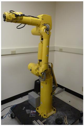
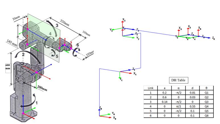
Figure 1
(left to right) Fanuc robot, Fanuc robot sketch with dimensions, Matlab simulation of robot in home configuration, and new DH table
Fanuc 3D Simulations:
The Fanuc robot was reconstructed in Matlab and used in all the simulations for validating algorithms for the Fanuc manipulator. A resolve rates algorithm is tested on the Fanuc 3d simulation shown below where it is commaned to move its end effector to a certain position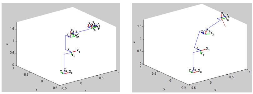
Figure 2: Simulation of the resolved rate algorithm where robot achieves desired position
Maxon Amplifier Trouble-Shooting:
A year previous to my arrival at A.R.M.A. lab, most electronics and wiring of the Fanuc robot was burnt out due to an undergrad students' mistake of reversing the polarity when supplying power to the robot. All damaged wiring had been replaced but the robot was not able to run ever since the incident. The six Maxon amplifiers, used to send and receive signals via a CAN bus system, have been wired in series and each has the role of reading encoder values and sending actuation signals to their respective motors. When the Fanuc robot was operated, encoder values were being read properly, but when commands were sent to actuate the robot, all the amplifier LEDs’ turn red, indicating some error within the system. It was assumed that the circuit boards of the Maxon amplifiers responsible for sending commands to the motors had been burnt out. The problem needed attention, each amplifier costs approximately 500$. I began the troubleshooting process by isolating each amplifier on its own in the xPC Simulink model, in addition, CAN bus communication guides and Maxon amplifier operation booklets were studied in order for me to revise the hardware setup of the Fanuc and ensure. Each isolated amplifier was wired to the Fanucs' 6th wrist motor since it has unlimited rotation and poses no threat of throwing the heavy robot around. After each amplifier was tested to be successful; it was concluded that the amplifier box was wired incorrectly after the incident of reversing polarity. The figure below shows proper wiring of the six Maxon amplifiers in series. The Fanuc robot once again runs properly.
Figure 3: 6 maxon amplifiers operating succesfully after trouble shooting (green lights)
Puma 3rd Link Image Digitization:
The DH parameters of Puma 560 robot 3rd link in A.R.M.A lab is an approximation of its real geometry. The center of rotation of this link is not located exactly in the symmetric center of the robots protective housing. There is an offset which has not been taken into consideration in the robots DH parameters used to operate it. The Puma robot was brought to A.R.M.A lab with unknown model identification number and no catalogue specifying link geometry.
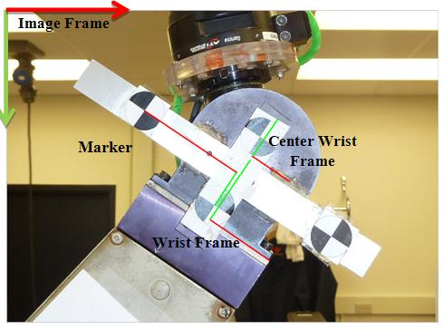
A written Matlab code defines frame of references of the image, marker, and wrist frame in order to relate them through homogeneous transforms. To find wrist frame center many points around its circumference were digitized and a least squares fit circle generated the coordinates of its center. While rotating the puma 3rd link and keeping other links stationary, a total of 32 different orientations were recorded by the Claron Micron Tracker; the position points were plotted in 3D space and a best fit plane was made in order to visualize the puma 3rd link plane of rotation. They were then run through a least squares circle fit in order to obtain the exact center of rotation.
![]()
Figure 4: (left to right)
Image Digitization of Coordinate frames. ,Claron Micron-Tracker H-40. Redline (x-axis) Green line (y-axis)
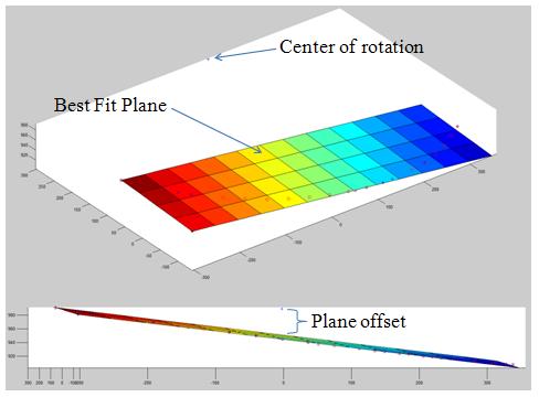
Figure 5: Plot best fit circle center of rotation, showing 32 measured poses of Puma 3rd link rotation (red o’s) and their projection on the best fit plane (blue x’s)
Finding Q-home values for Puma joints :
Each joint of the PUMA 560 is equipped with two transducers: an incremental encoder and a potentiometer. The commanded desired positions are calculated relative to the PUMA homed initial pose. When the robot is first run, it achieves home orientation from predefined potentiometer pot values; after which encoder signals are zeroed. The problem is that the home-position has been defined by the eyeballing technique where carved marks on the Puma’s 6 links are visually aligned, 6 pot values are recorded and input to a starting code so the Puma assumes this pose upon every run. A code was written by me where data values from the Claron Micron Tracker (measured position of end effector) and Puma joint values (used to calculate exact position of end effector ) are compared, matlab fmincon optimizer reduces error between exact and measured data by assigning Q-Home values which are then output to the user once the code is run.
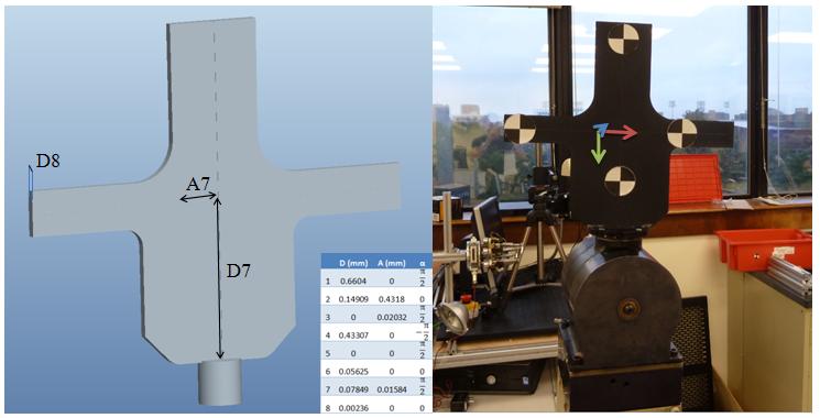
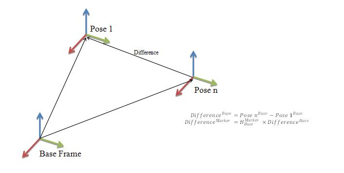
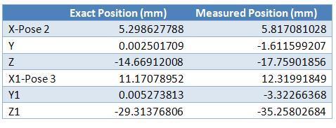
Figure 6: (Top left)
Marker Attachment for Puma Wrist made by Rapid Prototyping, Updated DH Table, Marker coordinate frame x axis (red), y axis (green), z axis (blue)
(Top Right) Theory of Transforming Measured/ Calculated values (from Claron Micron tracker and Direct Kinematics respectively) to Marker Frame
(Bottom) Results of exact and measured postions of Poses 2 and 3 after data has been transformed to Marker frame